


I am not going to be the first (or last) person to discuss the benefits associated with the current trend moving intelligence away from high power server farms in the cloud towards sensors embedded On The Edge™. Some of our latest projects have involved hardware like the Google Coral Edge TPU or Nvidia Jetson Nano, allowing us to extract meaningful information from sensors embedded directly on the factory floor or perform image classification. All this drawing much less power and consuming less bandwidth than traditional methods.
The sensors we develop generally have some amount of intelligence themselves, although in a traditional sense. The relatively high processing power included in modern microcontrollers allows for preprocessing, filtering, Fourier analysis, thresholding… Shaping and modelling their captured values into meaningful information. We’d read lots of hype about how ML was revolutionizing embedded systems, but were the frameworks mature enough for production environments? Was it easy enough to implement so as to not lose our sanity trying to get them to run?
Tensorflow Lite for Microcontrollers
After reading up on the Tensorflow Lite for Microcontrollers site, and Wezley Sherman’s post, Tensorflow, meet the ESP32 (╯°□°)╯︵ ┻━┻, it almost seemed too easy. The framework is available as an Arduino Library (Wezley gives great a guide on how to include it as a Platform IO library for the ESP32), and there are instructions to generate example projects with the necessary source files/headers for Adafruit or Sparkfun dev kits or popular microcontrollers such as the aforementioned ESP32 or STM32.
Since the date of publication of the post, the micro folder has been promoted outside of its old experimental parent. Currently (March 2020) the supported TARGET architectures as defined in the tensorflow/lite/micro/tools/make/targets folder include:
- apollo3evb
- arc
- bluepill
- ecm3531
- esp32
- hexagon
- leon
- linux_x86
- mbed
- mcu_riscv
- osx
- osx_x86_64
- stm32f4
- xtensa_xpg
The process starts with cloning the git repository (https://github.com/tensorflow/tensorflow.git) and running a command similar to:
sudo make -f tensorflow/lite/experimental/micro/tools/make/Makefile TARGET=esp generate_hello_world_esp_project
When the build finishes, you end up with a sample project in the folder:
tensorflow/lite/micro/tools/make/gen/esp_xtensa-esp32/prj/hello_world
The tfmicro subfolder contains all the necessary source files and headers necessary for creating an Espressif IoT Development Framework component library, to be included in your project. The generated component is configured for version 4.0 or above of the ESP-IDF; in our projects we are using the latest stable release (v3.3.1) so some modifications were required, as described in my git repo.
A Smart Battery Capacity Monitor
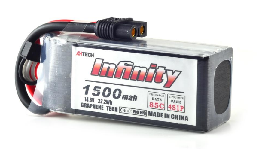
Our victim: a 4S 1500mAh LiPo battery
For one of our projects we designed a system that integrated voltage, current, temperature and humidity measurements through discrete sensors connected to an ESP32 microcontroller through the I2C bus. The data is filtered and averaged. Through preconfigured thresholds, alerts are sent to a TLS secured MQTT broker for event detection. Can we take advantage of Tensorflow Lite regression using this hardware?
Anyone who has flown a drone suffers from battery anxiety. LiPo batteries come with a nominal voltage (specified in units of “S” or multiples of 3.7V) and current capacity (with units of mA/h). As the batteries follow charge/discharge cycles, this nominal capacity is diminished, and with it the available time of flight.
Flight Controllers (FC from now on) monitor the instantaneous voltage on the battery leads, giving an estimate of the capacity depending on the voltage. With higher current loads and due to the energy dissipated (as heat) on the battery’s internal resistance, the voltage on the battery terminals drops, falsely signalling lower remaining capacity. If the FC includes a current measurement sensor, by simple integration the remaining capacity can also be calculated. This evidently depends on correctly setting the nominal capacity and/or current charge state/percent, and as the battery ages, this value becomes increasingly optimistic.
Our goal therefore is to attempt to obtain a better approximation of the remaining battery capacity through Machine Learning.
Implementation
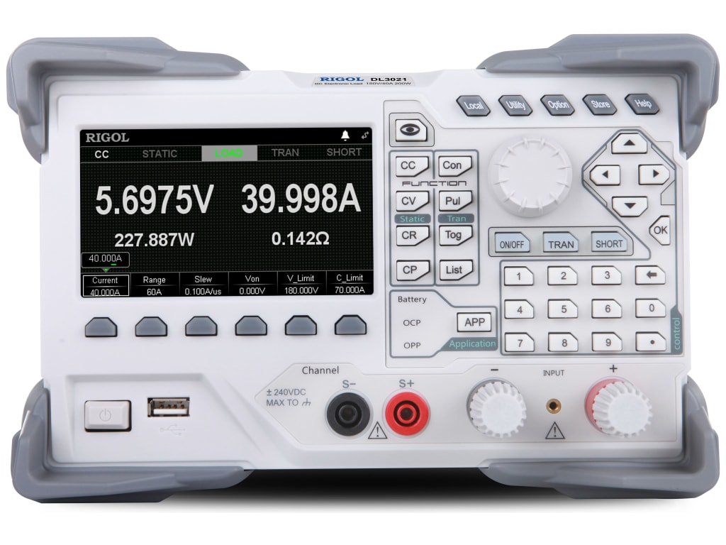
Rigol DL3021 Electronic Programmable Load
For building and training our regression model, we used a modified version of the Google hosted Basic Regression: Predict Fuel Efficiency tutorial, implemented on a local Jupyter netbook. Although the functionality for importing and preprocessing the dataset, building the model with Keras on Tensorflow 2.0 and running the inference was implemented as a Python module, the netbook gives a quick and easy interface to view the results of each one of the iterations of our design.
The first step in any regression problem is generating and collecting data into a dataset. For this purpose, we connected our LiPo battery to an electronically programmable load, which allows us to set a rate at which we will drain current from the battery, while monitoring the voltage. We programmed 8 different cycles of constant drain in increments of 1A (1A, 2A… 8A) cutting the cycle once the voltage had dropped to 13.3V to protect the battery. Temperature of the battery was measured with a thermocouple inserted into the plastic casing.
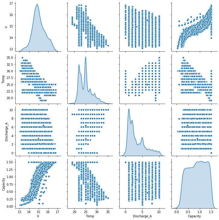
The variables identified as inputs were Temperature, Voltage and Discharge_A. As can be seen in the following seaborn cross correlation plot, there are obvious relationships between the estimated remaining Capacity and each of the inputs. In particular, the constant discharge current nature of our experimental setting can be observed when comparing Capacity and Discharge_A (vertical lines).
The Capacity remaining in the battery (measured by the amount of A/h still capable of being delivered) was calculated by integrating the discharge current for every successive interval and included as the label or value to predict.
After normalizing and randomly splitting into testing and training datasets, a simple regression model was built, since 1) the dataset was relatively small and 2) I wanted to make sure the model would fit into the esp32’s resources (flash and RAM, mainly).
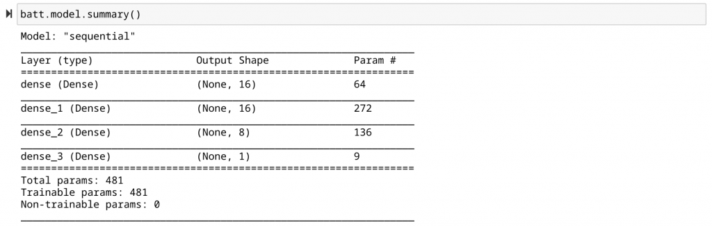
Simple model for training our Battery Capacity Predictor
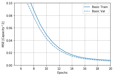
Running 50 epochs of the training series gives us a nice converging training and validation graph, with the training set just slightly above the validation set. Continuing the training for more epochs does not improve the Mean Square Error significantly, and we could easily run the risk of overfitting. The estimated precision of the predicted Capacity value is ±30mA/h, more than enough for our purposes.
Finally, it’s time to export the trained model to a format that can be compiled into an Esp32 firmware binary. The saveModel function of our class does this for us:
def saveModel(self):
        converter = tf.lite.TFLiteConverter.from_keras_model(self.model)
        converter.optimizations = [tf.lite.Optimize.OPTIMIZE_FOR_SIZE]
        tflite_model = converter.convert()
        open("./eai_batt_quantized.tflite", "wb").write(tflite_model)
The resulting tflite file needs to be converted into a c hex array with the command:
xxd -i eai_batt_quantized.tflite > eai_batt_quantized.cppMy version of the tflite component, on the current stable version of the ESP IDF framework at time of writing (v3.3.1) did not like this file as exported, and required some additional memory alignment and data type modifications. These were extracted from the sine_model_data.cc source files available in the TensorFlow lite tutorials. Note in particular the changes to the eai_batt_quantized_tflite and eai_batt_quantized_tflite_len variables types
#include "eai_batt_quantized.h"

// We need to keep the data array aligned on some architectures.
#ifdef __has_attribute
#define HAVE_ATTRIBUTE(x) __has_attribute(x)
#else
#define HAVE_ATTRIBUTE(x) 0
#endif
#if HAVE_ATTRIBUTE(aligned) || (defined(__GNUC__) && !defined(__clang__))
#define DATA_ALIGN_ATTRIBUTE __attribute__((aligned(4)))
#else
#define DATA_ALIGN_ATTRIBUTE
#endif

const unsigned char eai_batt_quantized_tflite[] DATA_ALIGN_ATTRIBUTE = {
0x1c, 0x00, 0x00, 0x00, 0x54, 0x46, 0x4c, 0x33, 0x00, 0x00, 0x12, 0x00,

// ... EXTRA LINES HERE

};
const unsigned int eai_batt_quantized_tflite_len = 5084;
To be able to use this model in our source code, a header is required to define the variables. Again, this is based on the sine_model_data.h header from the tutorial.
#ifndef BATT_QUANTIZED_MODEL_DATA_H_
#define BATT_QUANTIZED_MODEL_DATA_H_

extern const unsigned char eai_batt_quantized_tflite[];
extern const unsigned int eai_batt_quantized_tflite_len;

#endif
Since this is 2020 and the esp32 enjoys the benefits of c++ 14 compatibility, we encapsulated the functionality associated with the Tensorflow Lite regression into a class, SCTF, which runs a FreeRTOS task and provides a queue. The firmware’s main loop reads the relevant input data from each one of the sensors (in this case, a 4 channel ADS1115 ADC), puts them on an array and enqueues them onto the SCTF input queue.
void loop() {
    float value = NAN;

    TF_INPUT* inputs = new TF_INPUT(3);

    // get current time stamp
    int64_t ts = gettimestamp() / 1000LL;
    inputs->ts = ts;

    // READ VOLTAGE
    value = getADC(CHANNEL_A, VPS0);
    // send(TOPIC, "voltage_measured", value);
    inputs->values[0] = value;

    // READ TEMP
    //* not implemented yet
    inputs->values[1] = 25;
    // send(TOPIC, "temperatur_measured", value);

    // READ CURRENT
    value = getADC(CHANNEL_B, VPS1, OFF1);
    // send(TOPIC, "current_measured", value);
    inputs->values[2] = value;

    sctf->enqueue(inputs);
} // end loop
As can be seen in the code, the temperature sensor was not implemented in this experiment (I used a constant value of approximate room temperature, 25ºC). This is due to the fact that this was run one of our compact sensors that only had 2 of the 4 ADC channels exposed.
Inside the SCTF class, the relevant code is:
/** **********************************************************
* @brief Initialises the TF model, reserves memory and queue
*/
void SCRTF::build() {
constexpr int tensor_pool_size = 3 * 1024;
this->tensor_pool = new uint8_t[tensor_pool_size];
// Load the model to be used
this->batt_model = tflite::GetModel(eai_batt_quantized_tflite);
// Define ops resolver and error reporting
tflite::ops::micro::AllOpsResolver resolver;
tflite::ErrorReporter *error_reporter;
tflite::MicroErrorReporter micro_error;
error_reporter = µ_error;
// Instantiate the interpreter
static tflite::MicroInterpreter interpreter(this->batt_model, resolver, this->tensor_pool, tensor_pool_size, error_reporter);
this->interpreter = &interpreter;
// Allocate the the model's tensors in the memory pool that was created.
if (this->interpreter->AllocateTensors() != kTfLiteOk) {
ESP_LOGE(TAG, "There was an error allocating the memory");
return;
}
// Define input and output nodes
this->input_ = this->interpreter->input(0);
this->output_ = this->interpreter->output(0);
tf_queue = xQueueCreate(5, sizeof(float *));
for (int ix = 0; ix < TF_WINDOW_SIZE; ++ix) {
this->window.push_front((1.5 - SCRTF::mean_[3]) / SCRTF::std_[3]);
}
}
/** **********************************************************
* @brief Performs inference on given inputs, predicts Output
*
* @param inputs Contains an ordered list of values, with timestamp
*/
void SCRTF::infer(TF_INPUT *inputs) {
float *u = SCRTF::mean_;
float *s = SCRTF::std_;
// Normalization
float v = (inputs->values[0] - u[0]) / s[0];
float temp = (inputs->values[1] - u[1]) / s[1];
float A = (inputs->values[2] - u[2]) / s[2];
float capacity = NAN;
size_t window_length = this->window.size();
if (window_length == TF_WINDOW_SIZE) {
this->input_->data.f[0] = v;
this->input_->data.f[1] = temp;
this->input_->data.f[2] = A;
// inserts windowed data into the inputs
for (int ix = 0; ix < TF_WINDOW_SIZE; ++ix) {
this->input_->data.f[ix + 3] = window[ix];
}
// Run inference on the input data
if (this->interpreter->Invoke() != kTfLiteOk) {
ESP_LOGE(TAG, "There was an error invoking the interpreter!");
return;
}
// Print the output of the model.
capacity = this->output_->data.f[0];
// Runs callback function previously assigned to successful
// inference output (publishes to mqtt broker)
SCRTF::inference_callback_(inputs, capacity);
window.pop_back();
}
// Add new values to deque (inverse order as they get pushed back)
window.push_front((capacity - u[3]) / s[3]);
}A static member function was defined as a task which listens on the queue and calls the inference function once an input is received:
/** **********************************************************
 * @brief Main TF Inference task
 */
void SCRTF::task(void *) {
  SCRTF sctf;
  sctf.build();

  BaseType_t xStatus;
  TF_INPUT *inputs;
  while (true) {
    xStatus = xQueueReceive(tf_queue, &inputs, portMAX_DELAY);
    if (xStatus == pdTRUE) {
      sctf.infer(inputs);
    }
  }
}
Analysis and Conclusions
The input used for the validation of the model was a sequence of repeating cycles which alternated 55 seconds discharging at a rate of 2A with 5 seconds discharging at a rate of 8A. The sequence was stopped, as before, once the voltage reached 13.3V, as a safety measure to preserve the health of the battery.
To be able to quickly view and analyze the results, once the predicted value of remaining Capacity (in A/h) is obtained, it is sent over WiFi to an mqtt broker, fed into an InfluxDB database and plotted with a Grafana instance.
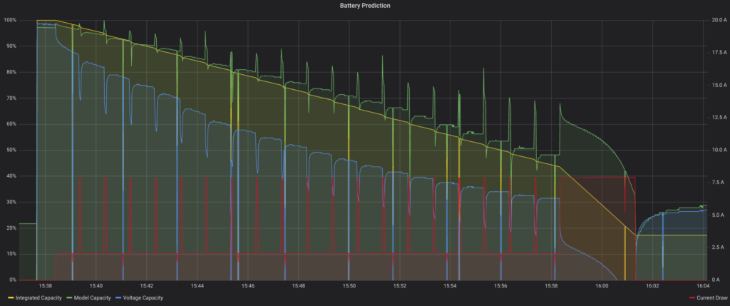
Alternating discharge 55s @ 2A, 5s @ 8A
In the graph you can see the TF Model Prediction (green) is following fairly closely the Integrated Values (yellow), except where the current (in red) transitions from 2A to 8A levels and back. This is specially visible during the last long 8A interval. The initial increase in current causes a spike in the predicted capacity, which then transitions in a slope similar to the predicted value, although with an offset.
One possible explanation is the fact that the training was done with a constant discharge rate, therefore the model has not been able to learn about these transitions. A possible solution would be to re-train the model with additional data that included more variations in the current consumption.
In blue is the naive approximate capacity expressed as a percentage of the voltage within the range of full capacity (16.8V) and depleted (13.3V). Clearly the predicted value is closer to the integrated series than the only-voltage approach, which also tends to underestimate the capacity with the initial current surge at the beginning of each 8A interval. This is similar to the effect obtained on a flight controller that signals a low battery alarm when the throttle is suddenly increased.
As mentioned, one limitation is that the node I used at the time did not have a temperature sensor configured, therefore the effects of the dissipated power on the temperature and as a consequence on the internal resistance could not be taken into account.
Of course, the regression model defined contains a series of simplifications that voids its use as a generic predictor for any type of LiPo battery, not just the particular unit we used to generate the dataset. To be able to apply this model to any battery, it would have to be able to take into account the internal resistance and it’s behaviour at different temperatures.
Possible solutions could be implementing a Recurrent Neural Network (RNN) including one or more LSTM layers into our Keras model. With this configuration it might be possible to estimate the internal resistance from voltage levels measured at different load situations, using this value as feedback to increment the precision of the estimates. Maybe in a next blog entry?
References:
- https://towardsdatascience.com/tensorflow-meet-the-esp32-3ac36d7f32c7
- https://www.hackster.io/news/easy-tinyml-on-esp32-and-arduino-a9dbc509f26c
- https://www.tensorflow.org/tutorials/keras/regression
- https://www.tensorflow.org/guide/keras/rnn
- https://github.com/eloquentarduino/EloquentTinyML
- https://towardsdatascience.com/pca-using-python-scikit-learn-e653f8989e60